Toyota Corolla Cross: Quarter Trim Speaker
Removal
REMOVAL
CAUTION / NOTICE / HINT
COMPONENTS (REMOVAL)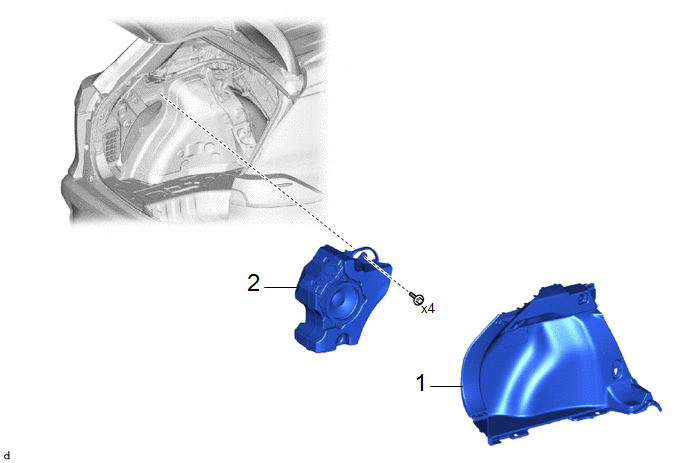
|
Procedure |
Part Name Code |
.png) |
.png) |
.png) |
|
|---|---|---|---|---|---|
|
1 |
DECK TRIM SIDE PANEL ASSEMBLY LH |
64740C |
- |
- |
- |
|
2 |
NO. 1 SPEAKER ASSEMBLY WITH BOX |
86150 |
- |
- |
- |
PROCEDURE
1. REMOVE DECK TRIM SIDE PANEL ASSEMBLY LH
Click here .gif)
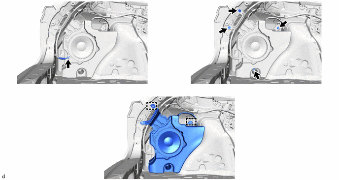
2. REMOVE NO. 1 SPEAKER ASSEMBLY WITH BOX
Inspection
INSPECTION
PROCEDURE
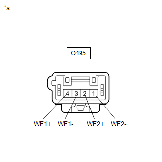
1. INSPECT NO. 1 SPEAKER ASSEMBLY WITH BOX
(a) Check the resistance.
|
(1) Measure the resistance according to the value(s) in the table below. Standard Resistance:
If the result is not as specified, replace the No. 1 speaker assembly with box. |
|
Installation
INSTALLATION
CAUTION / NOTICE / HINT
COMPONENTS (INSTALLATION)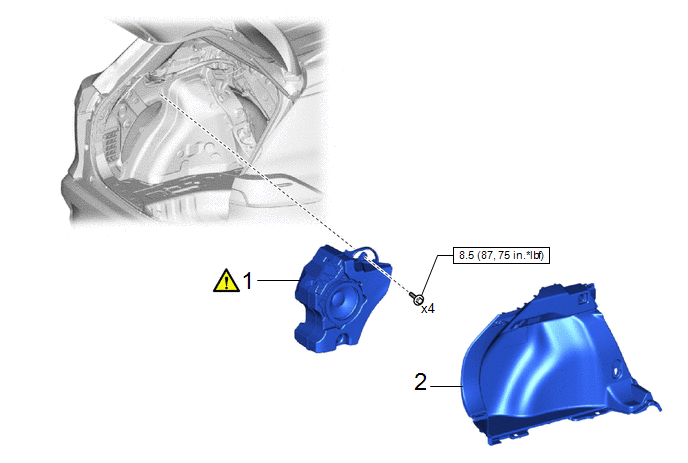
|
Procedure |
Part Name Code |
.png) |
.png) |
.png) |
|
|---|---|---|---|---|---|
|
1 |
NO. 1 SPEAKER ASSEMBLY WITH BOX |
86150 |
|
- |
- |
|
2 |
DECK TRIM SIDE PANEL ASSEMBLY LH |
64740C |
- |
- |
- |
.png) |
N*m (kgf*cm, ft.*lbf): Specified torque |
- |
- |
PROCEDURE
1. INSTALL NO. 1 SPEAKER ASSEMBLY WITH BOX
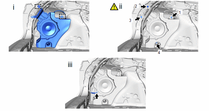
(1) Engage the guides to install the No. 1 speaker assembly with box.
(2) Install the 4 bolts in the order shown in the illustration.
Torque:
8.5 N·m {87 kgf·cm, 75 in·lbf}
(3) Connect the connector.
2. INSTALL DECK TRIM SIDE PANEL ASSEMBLY LH
Click here .gif)


