Toyota Corolla Cross: Parts Location
PARTS LOCATION
ILLUSTRATION
|
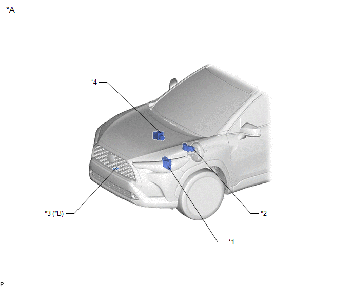
*A | for Gasoline Model |
*B | w/ Washer Fluid Level Warning System |
|
*1 | ECM |
*2 | BRAKE MASTER CYLINDER RESERVOIR ASSEMBLY - BRAKE FLUID LEVEL WARNING SWITCH |
|
*3 | LEVEL WARNING SWITCH ASSEMBLY |
*4 | BRAKE ACTUATOR ASSEMBLY - SKID CONTROL ECU |
ILLUSTRATION
|
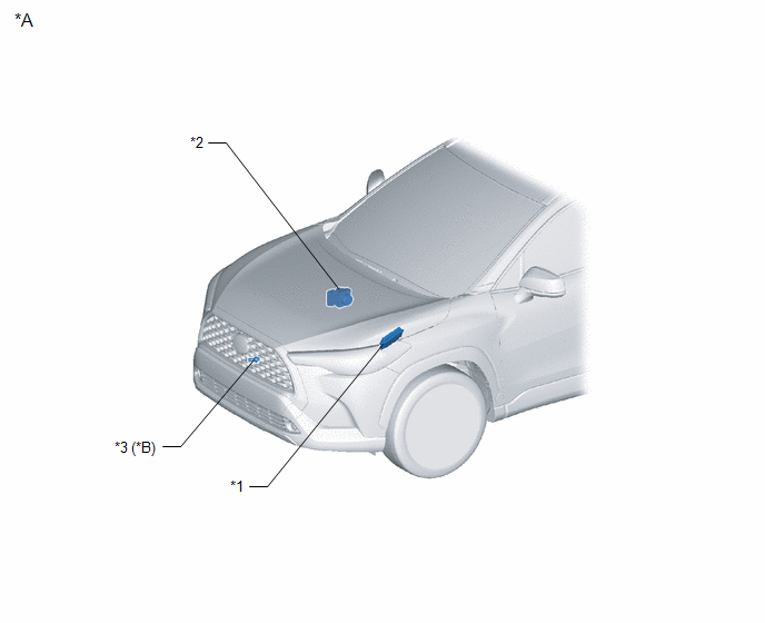
*A | for HEV Model |
*B | w/ Washer Fluid Level Warning System |
|
*1 | ECM |
*2 | BRAKE ACTUATOR ASSEMBLY - SKID CONTROL ECU |
|
*3 | LEVEL WARNING SWITCH ASSEMBLY |
- | - |
ILLUSTRATION
|
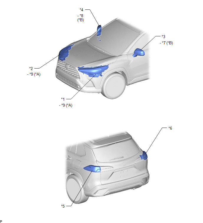
*A | for Bulb Type Clearance Light |
*B | w/ Side Turn Signal Light |
|
*1 | HEADLIGHT ASSEMBLY LH |
*2 | HEADLIGHT ASSEMBLY RH |
|
*3 | OUTER REAR VIEW MIRROR ASSEMBLY LH |
*4 | OUTER REAR VIEW MIRROR ASSEMBLY RH |
|
*5 | REAR COMBINATION LIGHT ASSEMBLY LH |
*6 | REAR COMBINATION LIGHT ASSEMBLY RH |
|
*7 | SIDE TURN SIGNAL LIGHT ASSEMBLY LH |
*8 | SIDE TURN SIGNAL LIGHT ASSEMBLY RH |
|
*9 | FRONT TURN SIGNAL LIGHT SOCKET |
- | - |
ILLUSTRATION
|
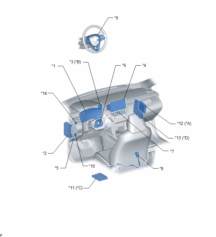
*A | w/ Smart Key System |
*B | w/o Smart Key System |
|
*C | w/ Stereo Component Amplifier |
*D | for HEV Model |
|
*1 | COMBINATION METER ASSEMBLY - MULTI-INFORMATION DISPLAY |
*2 | POWER DISTRIBUTION BOX ASSEMBLY - METER-IGR (for HEV Model) - HAZ FUSE |
|
*3 | TRANSPONDER KEY ECU ASSEMBLY |
*4 | RADIO AND DISPLAY RECEIVER ASSEMBLY |
|
*5 | DLC3 |
*6 | SPIRAL CABLE SUB-ASSEMBLY |
|
*7 | HAZARD WARNING SIGNAL SWITCH ASSEMBLY |
*8 | FRONT SEAT INNER BELT ASSEMBLY LH |
|
*9 | STEERING PAD SWITCH ASSEMBLY |
*10 | LIGHT CONTROL RHEOSTAT |
|
*11 | STEREO COMPONENT AMPLIFIER ASSEMBLY |
*12 | CERTIFICATION ECU (SMART KEY ECU ASSEMBLY) |
|
*13 | HYBRID VEHICLE CONTROL ECU |
*14 | STOP LIGHT SWITCH ASSEMBLY |
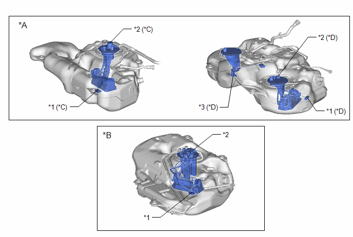
ILLUSTRATION
|
*A | for Gasoline Model |
*B | for HEV Model |
|
*C | for 2WD |
*D | for AWD |
|
*1 | FUEL SENDER GAUGE ASSEMBLY |
*2 | FUEL SUCTION TUBE WITH PUMP AND GAUGE ASSEMBLY |
|
*3 | FUEL TANK VENT TUBE ASSEMBLY - NO. 2 FUEL SENDER GAUGE ASSEMBLY |
- | - |
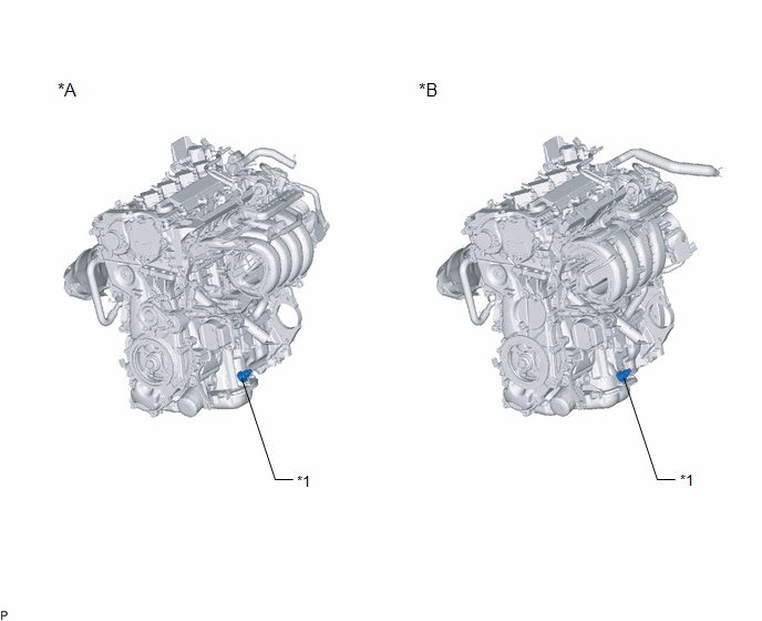
ILLUSTRATION
|
*A | for M20A-FKS |
*B | for M20A-FXS |
|
*1 | ENGINE OIL LEVEL SENSOR |
- | - |


