Toyota Corolla Cross: System Diagram
SYSTEM DIAGRAM
HINT:
Refer to System Diagram of CAN Communication System.
- for HEV Model:
Click here .gif)
- for Gasoline Model:
Click here
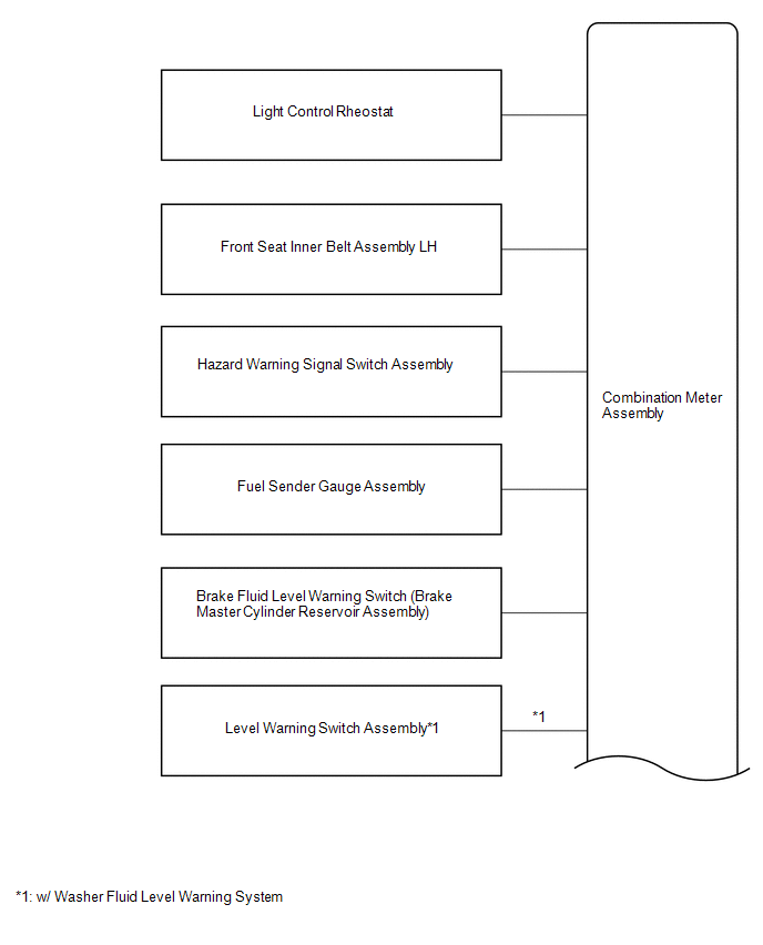
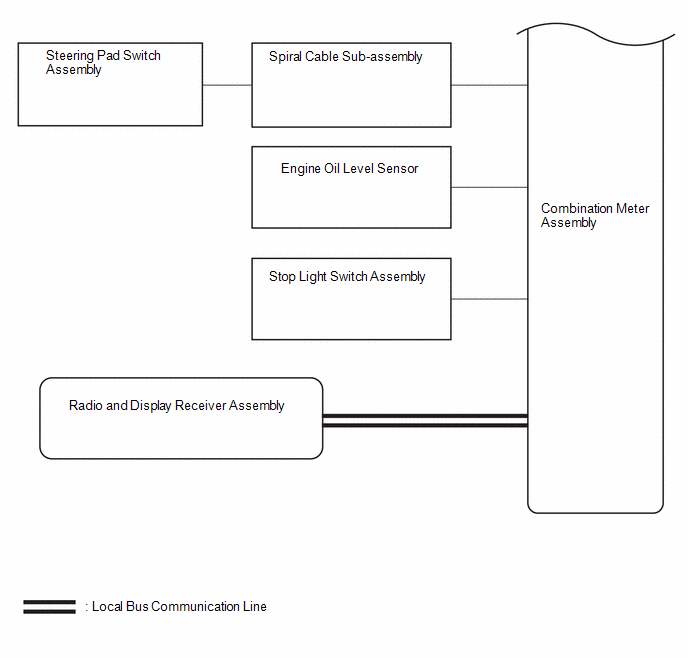
COMBINATION METER ASSEMBLY DIAGRAM
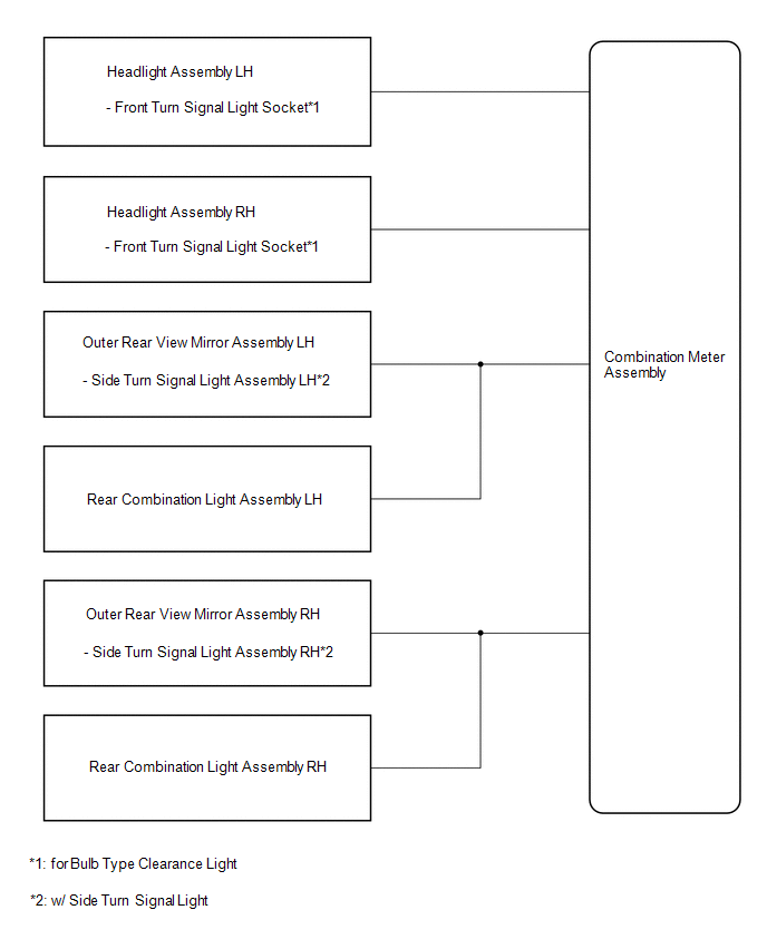
TURN SIGNAL LIGHT DIAGRAM
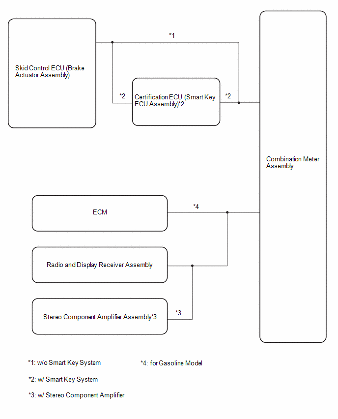
SPEED SIGNAL DIAGRAM
READ NEXT:
CAUTION / NOTICE / HINT
HINT:
Use the following procedure to troubleshoot the meter / gauge system.
*: Use the GTS.
PROCEDURE
1. VEHICLE BROUGHT TO WORKSHOP
NE
CUSTOMIZE PARAMETERS
NOTICE:
When the customer requests a change in a function, first make sure that the function can be customized.
Be sure to make a note of the current settings before cu
PROBLEM SYMPTOMS TABLE NOTICE: When replacing the combination meter assembly, always replace it with a new one. If a combination meter assembly which was installed to another vehicle is used, the info
SEE MORE:
DESCRIPTION
The TCM continuously monitors its monitor IC. If it detects an internal malfunction,
the TCM illuminates the MIL and stores this DTC.
DTC No.
Detection Item
DTC Detection Condition
Trouble Area
MIL
Memory
No
DESCRIPTION
Detection Item
Symptom
Trouble Area
Radio Receiver Assembly Communication Stop Mode
Communication stop for "Display and Navigation (AVN)" is indicated on
the "Communication Bus Check" screen of the GTS.


