
Toyota Corolla Cross: Installation
INSTALLATION
CAUTION / NOTICE / HINT
|
Procedure | Part Name Code |
.png) |
.png) |
 |
|---|---|---|---|---|---|
|
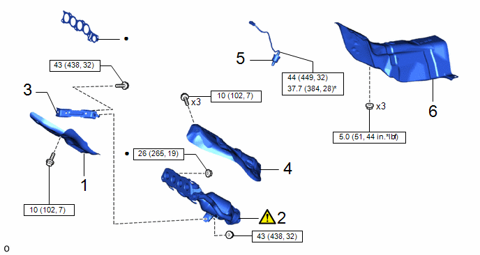
1 | NO. 2 EXHAUST MANIFOLD HEAT INSULATOR |
17168 | - |
- | - |
|
2 | EXHAUST MANIFOLD (TWC: Front Catalyst) |
17141 |
|
- | - |
|
3 | MANIFOLD STAY |
17118 | - |
- | - |
|
4 | NO. 1 EXHAUST MANIFOLD HEAT INSULATOR |
17167 | - |
- | - |
|
5 | AIR FUEL RATIO SENSOR |
89467B | - |
- | - |
|
6 | FRONT NO. 1 FLOOR HEAT INSULATOR |
58151 | - |
- | - |
.png) |
N*m (kgf*cm, ft.*lbf): Specified torque |
● | Non-reusable part |
|
* | For use with SST |
- | - |
|
Procedure | Part Name Code |
|
|
| |
|---|---|---|---|---|---|
|
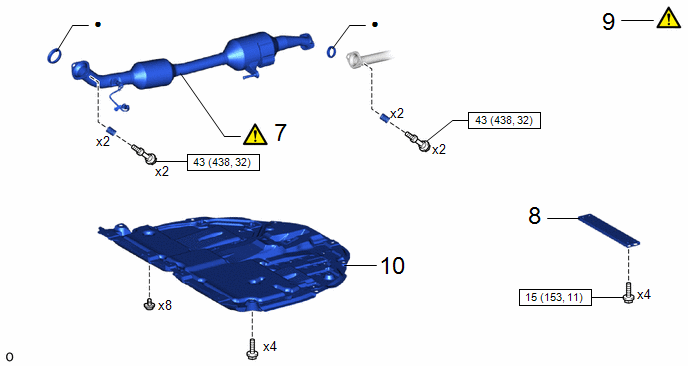
7 | FRONT EXHAUST PIPE ASSEMBLY (TWC: Rear Catalyst) |
17410 |
|
- | - |
|
8 | FRONT FLOOR CENTER BRACE |
57533B | - |
- | - |
|
9 | INSPECT FOR EXHAUST GAS LEAK |
- |
|
- | - |
|
10 | NO. 1 ENGINE UNDER COVER ASSEMBLY |
51410 | - |
- | - |
|
|
N*m (kgf*cm, ft.*lbf): Specified torque |
● | Non-reusable part |
PROCEDURE
1. INSTALL NO. 2 EXHAUST MANIFOLD HEAT INSULATOR
Torque:
10 N·m {102 kgf·cm, 7 ft·lbf}
2. INSTALL EXHAUST MANIFOLD (TWC: Front Catalyst)
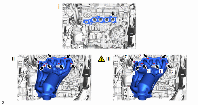
(1) Install a new exhaust manifold to head gasket to the cylinder head sub-assembly.
(2) Using a 12 mm deep socket wrench, temporarily install the exhaust manifold (TWC: Front Catalyst) to the cylinder head sub-assembly with 7 new nuts.
(3) Using the 12 mm deep socket wrench, tighten the 7 nuts in the order shown in the illustration.
Torque:
26 N·m {265 kgf·cm, 19 ft·lbf}
3. INSTALL MANIFOLD STAY

(1) Temporarily install the manifold stay to the exhaust manifold (TWC: Front Catalyst) and cylinder block sub-assembly with the bolt and nut.
(2) Tighten the bolt and nut in the order shown in the illustration.
Torque:
43 N·m {438 kgf·cm, 32 ft·lbf}
4. INSTALL NO. 1 EXHAUST MANIFOLD HEAT INSULATOR
Torque:
10 N·m {102 kgf·cm, 7 ft·lbf}
5. INSTALL AIR FUEL RATIO SENSOR
Click here .gif)
6. INSTALL FRONT NO. 1 FLOOR HEAT INSULATOR
Click here
7. INSTALL FRONT EXHAUST PIPE ASSEMBLY (TWC: Rear Catalyst)
.png)
|
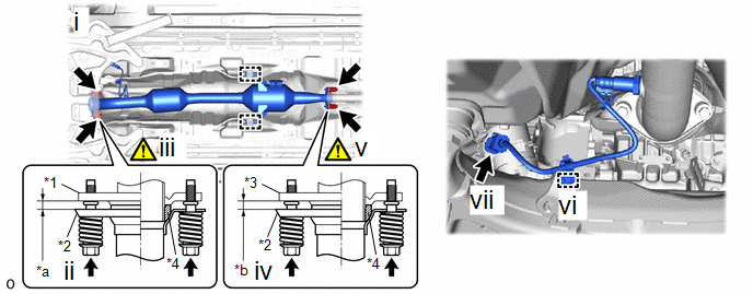
*1 | Exhaust Manifold (TWC: Front Catalyst) or Front Exhaust Pipe Assembly (TWC: Rear Catalyst) |
*2 | Gasket |
|
*a | Wooden Block |
*b | Plastic Hammer |
(1) Using a vernier caliper, measure the free length of the compression springs.
|
Standard Length (Front) | 43 mm (1.69 in.) |
|
Standard Length (Rear) |
40 mm (1.57 in.) |
|
Minimum Free Length (Front) |
41.5 mm (1.63 in.) |
|
Minimum Free Length (Rear) |
38.5 mm (1.52 in.) |
If the free length is less than the minimum, replace the compression spring.
(2) temporarily install 2 new gaskets to the exhaust manifold (TWC: Front Catalyst) and front exhaust pipe assembly (TWC: Rear Catalyst).
(3) Using a plastic hammer and wooden block, tap in each gasket until its surface is flush with the exhaust manifold (TWC: Front Catalyst) and front exhaust pipe assembly (TWC: Rear Catalyst).
NOTICE:
- Be sure to install the gasket in the correct direction.
- Do not reuse the gaskets.
- Do not damage the gaskets.
- Do not push in the gaskets by using the exhaust pipes when connecting them.
|
*1 | Exhaust Manifold (TWC: Front Catalyst) |
*2 | Front Exhaust Pipe Assembly (TWC: Rear Catalyst) |
|
*3 | Tail Exhaust Pipe Assembly |
*4 | Gasket |
|
*a | Space between Flanges: 8.5 mm (0.335in.) |
*b | Space between Flanges: 6.5 mm (0.256in.) |
(1) Connect the front exhaust pipe assembly to the 3 exhaust pipe supports.
(2) Install the front exhaust pipe assembly (TWC: Rear Catalyst) to the exhaust manifold (TWC: Front Catalyst) with the 2 compression springs and 2 bolts.
Torque:
43 N·m {438 kgf·cm, 32 ft·lbf}
(3) After installation, check that the space between the flanges of the exhaust manifold (TWC: Front Catalyst) and front exhaust pipe assembly (TWC: Rear Catalyst) is consistent front-to-rear and left-to-right.
(4) Install the front exhaust pipe assembly (TWC: Rear Catalyst) to the tail exhaust pipe assembly with the 2 compression springs and 2 bolts.
Torque:
43 N·m {438 kgf·cm, 32 ft·lbf}
(5) After installation, check that the space between the flanges of the front exhaust pipe assembly (TWC: Rear Catalyst) and tail exhaust pipe assembly is consistent front-to-rear and left-to-right.
(6) Engage the wire harness clamp.
(7) Connect the heated oxygen sensor connector.
8. INSTALL FRONT FLOOR CENTER BRACE
Torque:
15 N·m {153 kgf·cm, 11 ft·lbf}
9. INSPECT FOR EXHAUST GAS LEAK
|
|
Click here |
10. INSTALL NO. 1 ENGINE UNDER COVER ASSEMBLY
Click here


