Toyota Corolla Cross: Installation
INSTALLATION
CAUTION / NOTICE / HINT
COMPONENTS (INSTALLATION)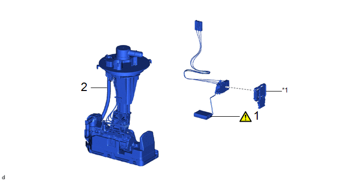
|
Procedure | Part Name Code |
.png) |
.png) |
 |
|---|---|---|---|---|---|
|
1 | FUEL SENDER GAUGE ASSEMBLY |
83320 |
|
- | - |
|
2 | FUEL SUCTION TUBE WITH PUMP AND GAUGE ASSEMBLY |
77020A | - |
- | - |
|
*1 | FUEL GAUGE BRACKET |
- | - |
PROCEDURE
1. INSTALL FUEL SENDER GAUGE ASSEMBLY
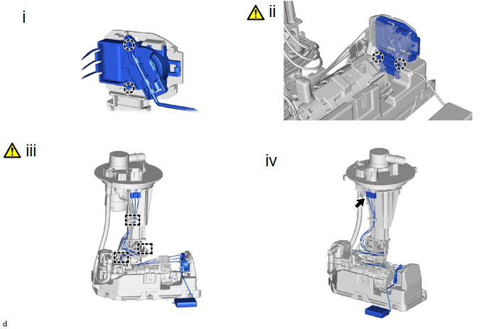
(1) Engage the 2 claws to install the fuel sender gauge assembly to the fuel gauge bracket.
(2) Engage the 2 claws to install the fuel gauge bracket with the fuel sender gauge assembly to the fuel suction tube with pump and gauge assembly.
NOTICE:
Be careful not to bend the arm of the fuel sender gauge assembly.
(3) Engage the 3 clamps to connect the wire harness to the fuel suction tube with pump and gauge assembly.
NOTICE:
- Do not damage the wire harness.
- When engaging each wire harness to the clamp, engage one wire at a time.
(4) Connect the fuel sender gauge assembly connector.
2. INSTALL FUEL SUCTION TUBE WITH PUMP AND GAUGE ASSEMBLY
Click here .gif)


