Toyota Corolla Cross: Inspection
INSPECTION
PROCEDURE
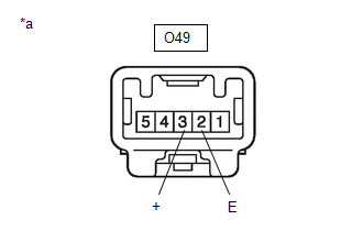
1. INSPECT FRONT SEAT INNER BELT ASSEMBLY (for Driver Side)
| (a) Measure the resistance according to the value(s) in the table below.
Standard Resistance: |
Tester Connection | Condition |
Specified Condition | |
O49-3(+) - O49-2(-) |
Driver side seat belt unfastened |
Below 1 Ω | |
Driver side seat belt fastened |
10 kΩ or higher | If the result is not as specified, replace the front seat inner belt assembly. |
 |
|
*a | Component without harness connected
(Front Seat Inner Belt Assembly) | | |
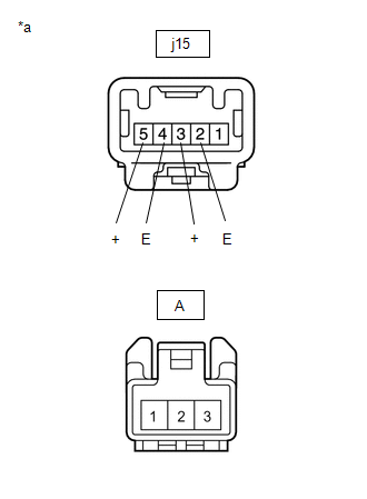
2. INSPECT FRONT SEAT INNER BELT ASSEMBLY (for Front Passenger Side)
| (a) Measure the resistance according to the value(s) in the table below (seat belt warning switch).
Standard Resistance: |
Tester Connection | Condition |
Specified Condition | |
j15-3(+) - j15-2(E) |
Front passenger side seat belt unfastened |
Below 1 Ω | | Front passenger side seat belt fastened |
10 kΩ or higher | If the result is not as specified, replace the front seat inner belt assembly. |
 |
|
*a | Component without harness connected
(Front Seat Inner Belt Assembly) | | |
(b) Measure the resistance according to the value(s) in the table below (occupant detection sensor line).
Standard Resistance:
|
Tester Connection | Condition |
Specified Condition |
|
j15-5(+) - A-1 | Always |
Below 1 Ω |
|
j15-4(E) - A-3 | Always |
Below 1 Ω |
If the result is not as specified, replace the front seat inner belt assembly.
READ NEXT:
INSTALLATION CAUTION / NOTICE / HINT COMPONENTS (INSTALLATION)
Procedure Part Name Code
1 FRONT SEAT INNER BELT ASSEMBLY
73230
- -
PRECAUTION CAUTION: Replace any faulty parts of the seat belt systems (outer belt, inner belt, bolts, nuts, adjustable shoulder anchor, tether anchor hardware and other related parts). When inspecting
SEE MORE:
CUSTOMIZE PARAMETERS CUSTOMIZE SMART KEY SYSTEM (for Start Function)
NOTICE:
When the customer requests a change in a function, first make sure that the function can be customized.
Record the current settings before customizing.
HINT: The following items can be customized. (a) Customi
INSTALLATION CAUTION / NOTICE / HINT COMPONENTS (INSTALLATION)
Procedure Part Name Code
1 INNER REAR VIEW MIRROR ASSEMBLY
87810
- -
2 NO. 1 FORWARD RECOGNITION COVER
86466D -
- -
3 NO. 2 FORWARD RECOGNI


