Toyota Corolla Cross: Inspection
INSPECTION
PROCEDURE
1. INSPECT SHIFT LOCK CONTROL ECU (w/ Smart Key System)
HINT:
If the results of the following inspections are as specified but a malfunction has occurred, replace the shift lock control unit assembly.
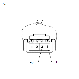
(a) Inspect wire harness:
|
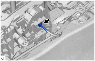
(1) Disconnect the shift lock control ECU connector. |
|
|
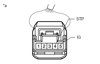
(2) Measure the voltage according to the value(s) in the table below. Standard Voltage:
|
|
(3) If the result is not as specified, repair or replace the shift lock control ECU wire harness.
|
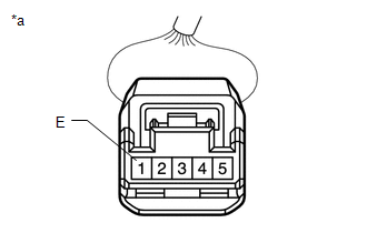
(4) Measure the resistance according to the value(s) in the table below. Standard Resistance:
|
|
(5) If the result is not as specified, repair or replace the shift lock control ECU wire harness.
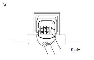
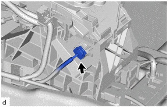
(b) Inspect shift lock solenoid:
|
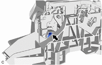
(1) Disconnect the shift lock solenoid connector. |
|
|
(2) Measure the resistance according to the value(s) in the table below. Standard Resistance:
|
|
(3) If the result is not as specified, replace the shift lock control unit assembly.
|
(4) Measure the resistance according to the value(s) in the table below. Standard Resistance:
|
|
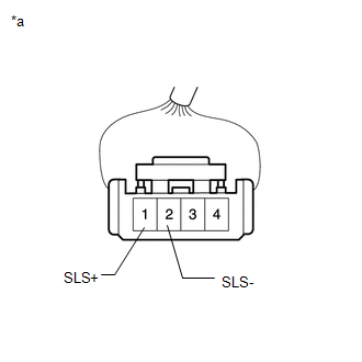
(5) If the result is not as specified, replace the shift lock control unit assembly.
2. INSPECT SHIFT LOCK CONTROL ECU (w/o Smart Key System)
HINT:
If the results of the following inspections are as specified but a malfunction has occurred, replace the shift lock control unit assembly.
(a) Inspect wire harness:
|
(1) Disconnect the shift lock control ECU connector. |
|
|
(2) Measure the voltage according to the value(s) in the table below. Standard Voltage:
|
|
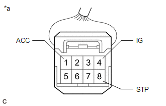
(3) If the result is not as specified, repair or replace the shift lock control ECU wire harness.
|
(4) Measure the resistance according to the value(s) in the table below. Standard Resistance:
|
|
(5) If the result is not as specified, repair or replace the shift lock control ECU wire harness.
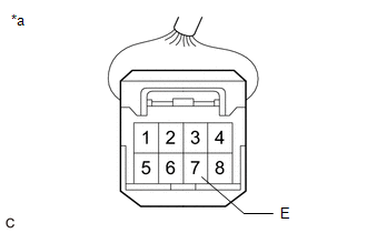
(b) Inspect key interlock solenoid operation signal:
|
(1) Connect the shift lock control ECU connector. |
|
|
(2) Measure the voltage according to the value(s) in the table below. Standard Resistance:
HINT: Do not disconnect the shift lock control ECU connector. |
|
(3) If the result is not as specified, replace the shift lock control unit assembly.
(c) Inspect shift lock solenoid:
|
(1) Disconnect the shift lock solenoid connector. |
|
|
(2) Measure the resistance according to the value(s) in the table below. Standard Resistance:
|
|
(3) If the result is not as specified, replace the shift lock control unit assembly.
|
(4) Measure the resistance according to the value(s) in the table below. Standard Resistance:
|
|
(5) If the result is not as specified, replace the shift lock control unit assembly.
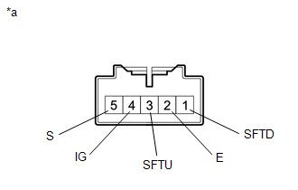
3. INSPECT TRANSMISSION CONTROL SWITCH
|
(a) Disconnect the transmission control switch connector. |
|
|
(b) Measure the resistance according to the value(s) in the table below. Standard Resistance:
|
|
(c) If the result is not as specified, replace the shift lock control unit assembly.


