Toyota Corolla Cross: Inspection
INSPECTION
PROCEDURE
1. INSPECT TRANSMISSION REVOLUTION SENSOR (NT)
(a) Connect the battery to the transmission revolution sensor (NT) as shown in the illustration.
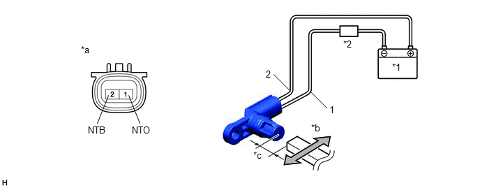
|
*1 |
Battery |
*2 |
Ammeter |
|
*a |
Component without harness connected (Transmission Revolution Sensor (NT)) |
*b |
Magnet |
|
*c |
5 mm (0.197 in.) or less |
- |
- |
(b) Wave a magnet left and right 5 mm (0.197 in.) or less from the tip of the transmission revolution sensor (NT) to output a high/low signal while measuring the current.
NOTICE:
Be sure to wave a magnetic object during the inspection. The current will not change without waving the magnetic object as indicated by the arrow in the illustration.
(c) Measure the current according to the value(s) in the table below.
Standard Current:
|
Tester Connection |
Condition |
Specified Condition |
|---|---|---|
|
1 (NTO) - 2 (NTB) |
Low signal |
4 to 8 mA |
|
High signal |
12 to 16 mA |
(d) If the result is not as specified, replace the transmission revolution sensor (NT).


