Toyota Corolla Cross: Entire Combination Meter does not Operate
DESCRIPTION
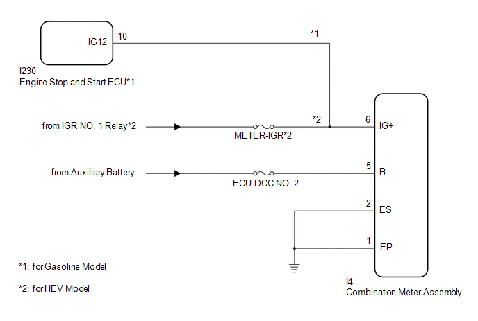
This circuit is the power source circuit for the combination meter assembly. This circuit provides two types of power sources; one is a constant power source, and the other is an IG power source.
WIRING DIAGRAM
CAUTION / NOTICE / HINT
NOTICE:
- When replacing the combination meter assembly, always replace it with a new one. If a combination meter assembly which was installed to another vehicle is used, the information stored in it will not match the information from the vehicle and a DTC may be stored.
- Inspect the fuses of circuits related to this system before performing the following procedure.
- When replacing the combination meter assembly, update the ECU security key.
Click here
PROCEDURE
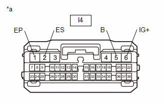
1. | CHECK HARNESS AND CONNECTOR (POWER SOURCE CIRCUIT) |
(a) Disconnect the combination meter assembly connector.
(b) Measure the resistance according to the value(s) in the table below.
Standard Resistance:
Tester Connection | Condition |
Specified Condition |
I4-1 (EP) - Body ground |
Always | Below 1 Ω |
I4-2 (ES) - Body ground |
Always | Below 1 Ω |
(c) Measure the voltage according to the value(s) in the table below.
Standard Voltage:
Tester Connection | Switch Condition |
Specified Condition |
I4-6 (IG+) - Body ground |
Ignition switch off |
Below 1 V |
Ignition switch ON*1 |
11 to 14 V |
Ignition switch ON*2 |
10.5 to 16 V |
I4-5 (B) - Body ground |
Ignition switch off |
11 to 14 V |
- *1: for HEV Model
- *2: for Gasoline Model
|
|
*a | Front view of wire harness connector
(to Combination Meter Assembly) | | |
OK |
| REPLACE COMBINATION METER ASSEMBLY |
NG |
| REPAIR OR REPLACE HARNESS OR CONNECTOR |
READ NEXT:
DESCRIPTION The combination meter assembly receives vehicle speed signals from the skid control ECU (brake actuator assembly) via CAN communication. The speed sensor detects the wheel speed and sends
DESCRIPTION for HEV Model:
The combination meter assembly receives engine speed signals from the hybrid vehicle control ECU via CAN communication. The combination meter assembly displays the engi
DESCRIPTION FUEL RECEIVER GAUGE OPERATION (a) OPERATION
The combination meter assembly uses the fuel sender gauge assembly to detect the amount of fuel remaining in the fuel tank assembly. The Hall
SEE MORE:
DESCRIPTION
Refer to DTC C051212
Click here
DTC No.
Detection Item
DTC Detection Condition
Trouble Area
MIL
DTC Output from
Note
C14E914
Right Rear Wheel Speed Sensor Supply Voltage Circuit
DESCRIPTION
DTC No. Detection Item
DTC Detection Condition Trouble Area
Warning Indicate Test Mode / Check Mode
B002013 Left Side Airbag Deployment Control Circuit Open
One of the following conditions is met:
The airbag ECU assembly detects an open in t