Toyota Corolla Cross: Door Control Switch (for Front Passenger Side)
Removal
REMOVAL
CAUTION / NOTICE / HINT
COMPONENTS (REMOVAL)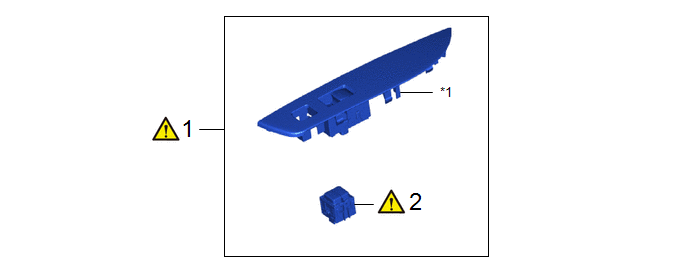
|
Procedure | Part Name Code |
.png) |
.png) |
 |
|---|---|---|---|---|---|
|
1 | POWER WINDOW REGULATOR SWITCH ASSEMBLY WITH FRONT DOOR ARMREST BASE UPPER PANEL RH |
- |
|
- | - |
|
2 | DOOR CONTROL SWITCH ASSEMBLY |
84930P |
|
- | - |
.gif)
|
*1 | FRONT DOOR ARMREST BASE UPPER PANEL RH |
- | - |
PROCEDURE
1. REMOVE POWER WINDOW REGULATOR SWITCH ASSEMBLY WITH FRONT DOOR ARMREST BASE UPPER PANEL RH
|
|
Click here |
2. REMOVE DOOR CONTROL SWITCH ASSEMBLY

(1) Using a screwdriver with its tip wrapped in protective tape, disengage the claws to remove the door control switch assembly.
Inspection
INSPECTION
PROCEDURE
1. INSPECT DOOR CONTROL SWITCH ASSEMBLY
| (a) Check the the resistance of the door control switch assembly. (1) Measure the resistance according to the value(s) in the table below. Standard Resistance:
If the result is not as specified, replace the door control switch assembly. |
|
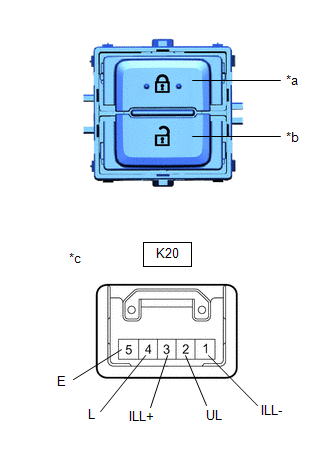
(b) Check that the switch illuminates.
(1) Apply battery voltage to the door control switch assembly and check that the switch illuminates.
OK:
|
Measurement Condition | Specified Condition |
|---|---|
|
Battery positive (+) → K20-3 (ILL+) Battery negative (-) → K20-1 (ILL-) |
Illuminates |
If the result is not as specified, replace the door control switch assembly.
Installation
INSTALLATION
CAUTION / NOTICE / HINT
COMPONENTS (INSTALLATION)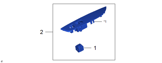
|
Procedure | Part Name Code |
.png) |
.png) |
 |
|---|---|---|---|---|---|
|
1 | DOOR CONTROL SWITCH ASSEMBLY |
84930P | - |
- | - |
|
2 | POWER WINDOW REGULATOR SWITCH ASSEMBLY WITH FRONT DOOR ARMREST BASE UPPER PANEL RH |
- | - |
- | - |
|
*1 | FRONT DOOR ARMREST BASE UPPER PANEL RH |
- | - |
PROCEDURE
1. INSTALL DOOR CONTROL SWITCH ASSEMBLY
2. INSTALL POWER WINDOW REGULATOR SWITCH ASSEMBLY WITH FRONT DOOR ARMREST BASE UPPER PANEL RH


