Toyota Corolla Cross: DCM Data Signal Circuit between Radio Receiver and DCM
DESCRIPTION
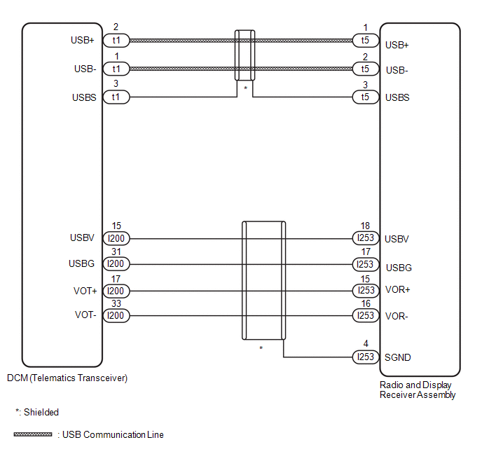
This circuit is used to send and receive signals between the DCM (telematics transceiver) and the radio and display receiver assembly.
WIRING DIAGRAM
PROCEDURE
|
1. |
CHECK HARNESS AND CONNECTOR (DCM [TELEMATICS TRANSCEIVER] - RADIO AND DISPLAY RECEIVER ASSEMBLY) |
(a) Disconnect the I253 and t5 radio and display receiver assembly.
(b) Disconnect the I200 and t1 DCM (telematics transceiver) connector.
(c) Measure the resistance according to the value(s) in the table below.
Standard Resistance:
|
Tester Connection |
Condition |
Specified Condition |
|---|---|---|
|
t5-1 (USB+) - t1-2 (USB+) |
Always |
Below 1 Ω |
|
t5-2 (USB-) - t1-1 (USB-) |
Always |
Below 1 Ω |
|
t5-3 (USBS) - t1-3 (USBS) |
Always |
Below 1 Ω |
|
I253-18 (USBV) - I200-15 (USBV) |
Always |
Below 1 Ω |
|
I253-17 (USBG) - I200-31 (USBG) |
Always |
Below 1 Ω |
|
I253-15 (VOR+) - I200-17 (VOT+) |
Always |
Below 1 Ω |
|
I253-16 (VOR-) - I200-33 (VOT-) |
Always |
Below 1 Ω |
|
t5-1 (USB+) - Body ground |
Always |
10 kΩ or higher |
|
t5-2 (USB-) - Body ground |
Always |
10 kΩ or higher |
|
t5-3 (USBS) - Body ground |
Always |
10 kΩ or higher |
|
I253-18 (USBV) - Body ground |
Always |
10 kΩ or higher |
|
I253-17 (USBG) - Body ground |
Always |
10 kΩ or higher |
|
I253-15 (VOR+) - Body ground |
Always |
10 kΩ or higher |
|
I253-16 (VOR-) - Body ground |
Always |
10 kΩ or higher |
|
I253-4 (SGND) - Body ground |
Always |
10 kΩ or higher |
| OK | .gif)
|
PROCEED TO NEXT SUSPECTED AREA SHOWN IN PROBLEM SYMPTOMS TABLE |
| NG |
|
REPAIR OR REPLACE HARNESS OR CONNECTOR |


