Toyota Corolla Cross: Charging Failure
PROCEDURE
|
1. |
CHECK GENERATOR PULLEY WITH CLUTCH (ON-VEHICLE INSPECTION) |
(a) Start the engine and visually check that the generator rotor assembly (fan) in the generator assembly is operating.
OK:
The generator rotor assembly (fan) is operating.
| NG | .gif) |
REPLACE GENERATOR PULLEY WITH CLUTCH |
|
.gif)
|
2. |
CHECK GENERATOR PULLEY WITH CLUTCH (UNIT INSPECTION) |
(a) Remove the generator assembly.
Click here .gif)
(b) Check the installation condition of the generator pulley cap.
OK:
The generator pulley cap is not loose or missing.
(c) Check for forming of particles due to friction (for dry type pulley) or grease leaks (for wet type pulley).
OK:
There are no large amounts of particles (for dry type pulley) or grease leaks (for wet type pulley).
(d) Check the generator pulley with clutch for misalignment (interference with the generator assembly).
OK:
The generator pulley with clutch is not misaligned (no interference with the generator assembly).
|
(e) Turn the generator pulley with clutch clockwise and counterclockwise by hand and check for noise. OK: Noise does not occur when turned in either direction. |
|
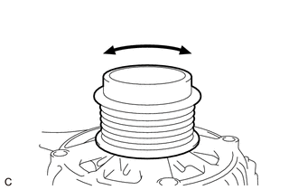
(f) Turn the generator pulley with clutch clockwise and counterclockwise by hand and visually check for runout.
OK:
The generator pulley with clutch does not have runout.
(g) Inspect generator pulley with clutch.
Click here
| OK | |
REPAIR OR REPLACE GENERATOR ASSEMBLY |
| NG | |
REPLACE GENERATOR PULLEY WITH CLUTCH |


