Toyota Corolla Cross Owners & Service Manuals

Toyota Corolla Cross: Seat Heater Switch

Removal

REMOVAL

CAUTION / NOTICE / HINT
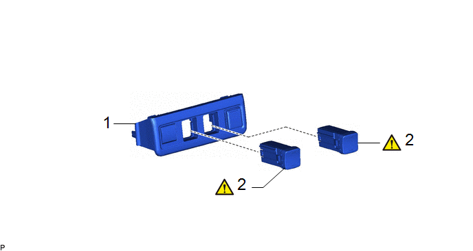
Procedure

Part Name Code

1

SWITCH BASE

55449D

-

-

-

2

REMOVE SEAT HEATER SWITCH

84751F

-

-

PROCEDURE

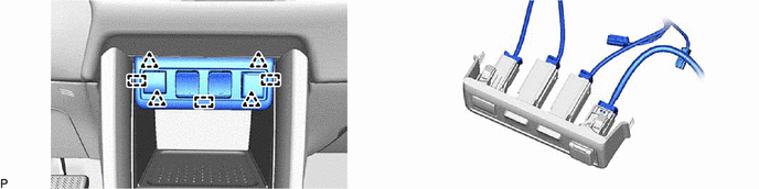
1. REMOVE SWITCH BASE

2. REMOVE SEAT HEATER SWITCH (for LH Side)
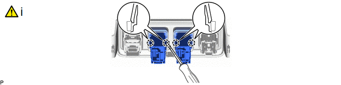
(1) Using a screwdriver with its tip wrapped with protective tape, disengage the claws and remove the steering heater switch.

Inspection

INSPECTION

PROCEDURE

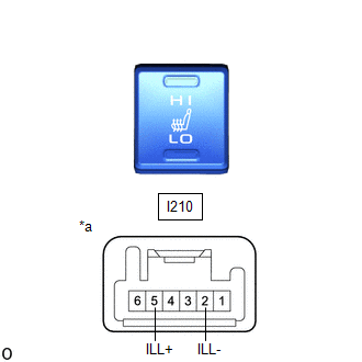
1. INSPECT SEAT HEATER SWITCH (for LH Side)

(a) Inspect the illumination operation.

(1) Apply auxiliary battery voltage to the seat heater switch connector, and check that the seat heater switch LED illuminates.

OK:

Auxiliary Battery Connection

Specified Condition

If the result is not as specified, replace the seat heater switch.

Auxiliary battery positive (+) → I210-5 (ILL+)

Auxiliary battery negative (-) → I210-2 (ILL-)

LED illuminates

*a

Component without harness connected

(Seat Heater Switch)

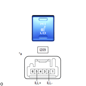
2. INSPECT SEAT HEATER SWITCH (for RH Side)

(a) Inspect the illumination operation.

(1) Apply auxiliary battery voltage to the seat heater switch connector, and check that the seat heater switch LED illuminates.

OK:

Auxiliary Battery Connection

Specified Condition

If the result is not as specified, replace the seat heater switch.

Auxiliary battery positive (+) → I209-5 (ILL+)

Auxiliary battery negative (-) → I209-2 (ILL-)

LED illuminates

*a

Component without harness connected

(Seat Heater Switch)

Installation

INSTALLATION

CAUTION / NOTICE / HINT
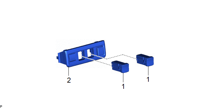
Procedure

Part Name Code

1

INSTALL SEAT HEATER SWITCH

84751F

-

-

-

2

SWITCH BASE

55449D

-

-

-

PROCEDURE

1. INSTALL SEAT HEATER SWITCH (for LH Side)

2. INSTALL SWITCH BASE

    READ NEXT:

     Seat Heater System

     Parts Location

    PARTS LOCATION ILLUSTRATION *1 SEAT HEATER SWITCH (for LH) *2 SEAT HEATER SWITCH (for RH) *3 POWER DISTRIBUTION BOX ASSEMBLY - PANEL FUSE - S/HTR F/L FUSE - S/HTR F/R

     System Diagram

    SYSTEM DIAGRAM for Driver Seat for Front Passenger Seat

    SEE MORE:

     Internal Control Module Throttle Position Performance Internal Electronic Failure (P060E49)

    MONITOR DESCRIPTION The ECM monitors the signals received from the No. 1 throttle position sensor. As the ECM monitors the VTA1 signal of the No. 1 throttle position sensor, if these signals do not correlate, a DTC will be stored. DTC No. Detection Item DTC Detection Condition Trouble

     Precaution

    PRECAUTION WHEN USING GTS CAUTION: Strictly obey all traffic rules and regulations. Do not drive the vehicle with the GTS cable contacting the pedals, shift lever or steering wheel. Driving the vehicle with the GTS cable contacting these areas could impede vehicle control, resulting

    © 2020-2026 Copyright www.tcorollacross.com PT NL