Toyota Corolla Cross: Removal
REMOVAL
CAUTION / NOTICE / HINT
COMPONENTS (REOVAL)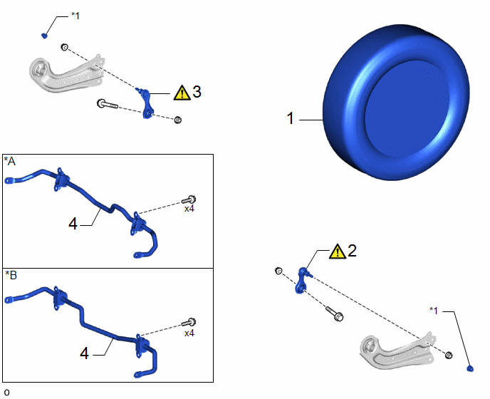
|
Procedure |
Part Name Code |
.png) |
.png) |
.png) |
|
|---|---|---|---|---|---|
|
1 |
REAR WHEEL |
- |
- |
- |
- |
|
2 |
REAR STABILIZER LINK ASSEMBLY LH |
48840A |
|
- |
- |
|
3 |
REAR STABILIZER LINK ASSEMBLY RH |
48830D |
|
- |
- |
|
4 |
REAR STABILIZER BAR |
48812 |
- |
- |
- |
|
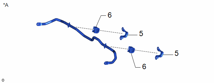
*A |
for Gasoline Model |
*B |
for HEV Model |
|
*1 |
CAP |
- |
- |
|
Procedure |
Part Name Code |
|
|
|
|
|---|---|---|---|---|---|
|
5 |
REAR NO. 1 STABILIZER BAR BRACKET |
48832A |
- |
- |
- |
|
6 |
REAR STABILIZER BAR BUSH |
48818 |
- |
- |
- |
|
*A |
for Gasoline Model |
- |
- |
PROCEDURE
1. REMOVE REAR WHEEL
Click here .gif)
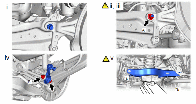
2. REMOVE REAR STABILIZER LINK ASSEMBLY LH
|
*a |
Wooden Block |
*b |
Jack |
(1) Remove the cap.
(2) Loosen the nut (A) of the rear stabilizer link assembly LH.
(3) If the ball joint turns together with the nut, use a 6 mm hexagon socket wrench to hold the stud bolt.
(4) Loosen the nut (B) of the rear stabilizer link assembly LH.
(5) Using a jack and a wooden block, support the rear No. 2 suspension arm assembly.
NOTICE:
- When jacking up the rear No. 2 suspension arm assembly, be sure to jack it up slowly.
- Make sure to perform this operation with the vehicle kept as low as possible.
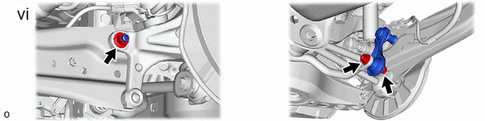
(6) Remove the bolt, 2 nuts and rear stabilizer link assembly LH.
3. REMOVE REAR STABILIZER LINK ASSEMBLY RH
(a) Perform the same procedure as for the LH side.
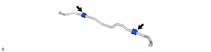
4. REMOVE REAR STABILIZER BAR
(a) for Gasoline Model:

(b) for HEV Model:

5. REMOVE REAR NO. 1 STABILIZER BAR BRACKET (for Gasoline Model)
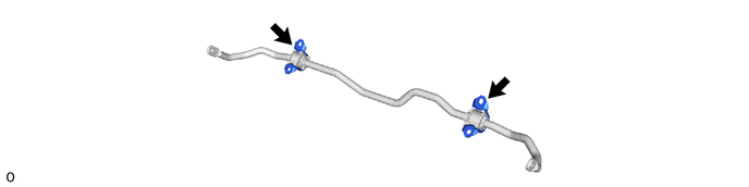
6. REMOVE REAR STABILIZER BAR BUSH (for Gasoline Model)