Toyota Corolla Cross: Removal
REMOVAL
CAUTION / NOTICE / HINT
COMPONENTS (REMOVAL)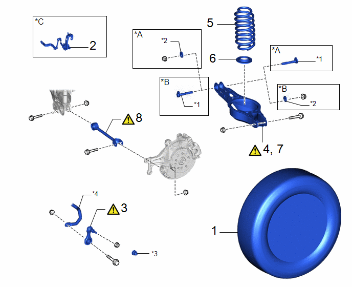
|
Procedure |
Part Name Code |
.png) |
.png) |
.png) |
|
|---|---|---|---|---|---|
|
1 |
REAR WHEEL |
- |
- |
- |
- |
|
2 |
REAR HEIGHT CONTROL SENSOR SUB-ASSEMBLY LH |
89408C |
- |
- |
- |
|
3 |
REAR STABILIZER LINK ASSEMBLY |
48840A |
|
- |
- |
|
4 |
SEPARATE REAR NO. 2 SUSPENSION ARM ASSEMBLY |
48740F |
|
- |
- |
|
5 |
REAR COIL SPRING |
48231B |
- |
- |
- |
|
6 |
REAR LOWER COIL SPRING INSULATOR |
48258C |
- |
- |
- |
|
7 |
REMOVE REAR NO. 2 SUSPENSION ARM ASSEMBLY |
48740F |
|
- |
- |
|
8 |
REAR NO. 1 SUSPENSION ARM ASSEMBLY |
48720A |
|
- |
- |
|
*A |
for Gasoline Model |
*B |
for HEV Model |
|
*C |
for LH Side |
- |
- |
|
*1 |
REAR SUSPENSION TOE ADJUST CAM SUB-ASSEMBLY |
*2 |
NO. 2 CAMBER ADJUST CAM |
|
*3 |
CAP |
*4 |
REAR STABILIZER BAR |
CAUTION / NOTICE / HINT
The necessary procedures (adjustment, calibration, initialization, or registration) that must be performed after parts are removed and installed, or replaced during rear suspension arm assembly removal/installation are shown below.
Necessary Procedures After Procedure Performed|
Replaced Part or Performed Procedure |
Necessary Procedure |
Effect/Inoperative Function when Necessary Procedure not Performed |
Link |
|---|---|---|---|
|
Rear wheel alignment adjustment |
for HEV Model:
|
|
|
for Gasoline Model:
|
|
|
|
for Gasoline Model AWD:
|
Dynamic torque control AWD system |
|
|
|
Suspension, tires, etc. |
Rear television camera assembly optical axis (Back camera position setting) |
Parking Assist Monitor System |
|
|
Initialize headlight ECU subassembly LH |
Automatic headlight beam level control system |
|
HINT:
- Use the same procedure for the RH side and LH side.
- The following procedure is for the LH side.
PROCEDURE
1. REMOVE REAR WHEEL
Click here .gif)
2. REMOVE REAR HEIGHT CONTROL SENSOR SUB-ASSEMBLY LH (w/ Height Control Sensor)
for LH Side:
Click here
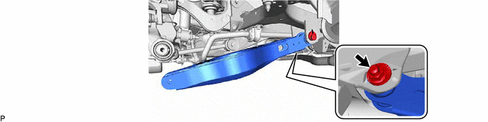
3. REMOVE REAR STABILIZER LINK ASSEMBLY
|
|
Click here |
4. SEPARATE REAR NO. 2 SUSPENSION ARM ASSEMBLY
|
|
Click here |
5. REMOVE REAR COIL SPRING
|
|
Click here |
6. REMOVE REAR LOWER COIL SPRING INSULATOR
Click here
7. REMOVE REAR NO. 2 SUSPENSION ARM ASSEMBLY
|
|
NOTICE: Hold the rear suspension toe adjust cam subassembly while rotating the nut. |
(a) for Gasoline Model:
(b) for HEV Model:

8. REMOVE REAR NO. 1 SUSPENSION ARM ASSEMBLY
|
|
NOTICE: Loosen the bolt with the nut secured. |