
Toyota Corolla Cross: Installation
INSTALLATION
CAUTION / NOTICE / HINT
COMPONENTS (INSTALLATION)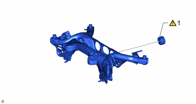
|
Procedure |
Part Name Code |
.png) |
.png) |
.png) |
|
|---|---|---|---|---|---|
|
1 |
REAR NO. 1 DIFFERENTIAL MOUNT CUSHION |
41651 |
|
- |
- |
|
Procedure |
Part Name Code |
|
|
|
|
|---|---|---|---|---|---|
|
2 |
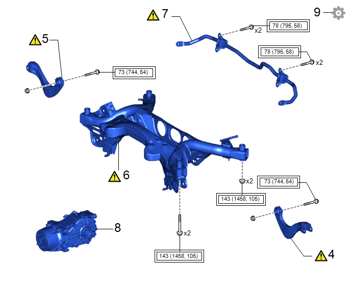
REAR UPPER CONTROL ARM ASSEMBLY LH |
48790 |
|
- |
- |
|
3 |
REAR UPPER CONTROL ARM ASSEMBLY RH |
48770A |
|
- |
- |
|
4 |
REAR SUSPENSION MEMBER SUB-ASSEMBLY |
51206A |
|
- |
- |
|
5 |
REAR STABILIZER BAR |
48812 |
|
- |
- |
|
6 |
REAR DIFFERENTIAL CARRIER SUB-ASSEMBLY |
41101 |
- |
- |
- |
|
7 |
INSPECT AND ADJUST REAR WHEEL ALIGNMENT |
- |
|
- |
- |
.png) |
Tightening torque for "Major areas involving basic vehicle performance such as moving/turning/stopping" : N*m (kgf*cm, ft.*lbf) |
- |
- |
PROCEDURE
1. INSTALL REAR NO. 1 DIFFERENTIAL MOUNT CUSHION
|
|
Click here |
2. INSTALL REAR UPPER CONTROL ARM ASSEMBLY LH
|
|
Click here |
3. INSTALL REAR UPPER CONTROL ARM ASSEMBLY RH
4. INSTALL REAR SUSPENSION MEMBER SUB-ASSEMBLY
|
*a |
Engine Lifter |
*b |
Attachment |
.png) |
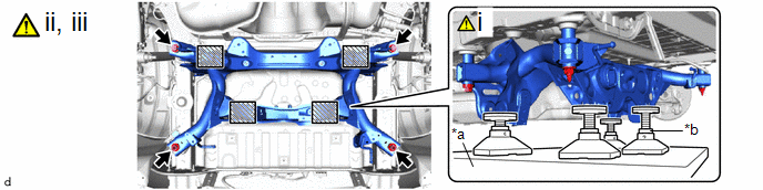
Attachment and Wooden Block Placement Location |
- |
- |
(1) Using an engine lifter and 4 attachments or equivalent tools, support the rear suspension member sub-assembly as shown in the illustration.
CAUTION:
- The rear suspension member sub-assembly is a very heavy component.
Make sure that it is supported securely.
- If the rear suspension member sub-assembly is not securely supported, it may drop, resulting in serious injury.
.png)
NOTICE:
- Use attachments and wooden blocks to keep the rear suspension member sub-assemblylevel.
- Keep supporting the rear suspension member sub-assembly until the installation has been completed.
(2) Raise the rear suspension member sub-assembly until there is no clearance between the rear suspension member sub-assembly and vehicle.
(3) Install the rear suspension member sub-assembly with the 2 bolts and 2 nuts.
Torque:
143 N·m {1458 kgf·cm, 105 ft·lbf}
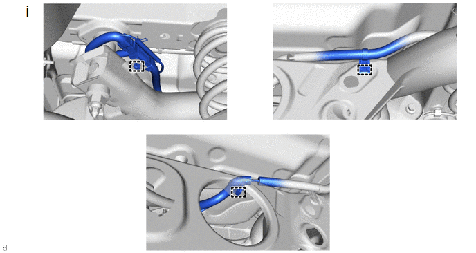
(1) Engage the 3 clamps to install the differential carrier wire harness.
5. INSTALL REAR STABILIZER BAR
|
|
Click here |
6. INSTALL REAR DIFFERENTIAL CARRIER SUB-ASSEMBLY
Click here .gif)
7. INSPECT AND ADJUST REAR WHEEL ALIGNMENT
Click here


