Toyota Corolla Cross: Inspection
INSPECTION
PROCEDURE
1. INSPECT FRONT SEAT ADJUSTER ASSEMBLY
(a) Check the operation of the slide motor.
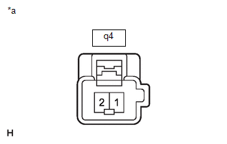
| (1) Check that the seat cushion moves smoothly when the auxiliary battery is connected to the slide motor connector terminals.
OK: |
Auxiliary Battery Connection |
Operational Direction | | Auxiliary battery positive (+) → q4-2
Auxiliary battery negative (-) → q4-1 |
Seat cushion moves forward | |
Auxiliary battery positive (+) → q4-1 Auxiliary battery negative (-) → q4-2 |
Seat cushion moves backward | If the result is not as specified, replace the front seat adjuster assembly. |
 |
|
*a | Component without harness connected
(Slide Motor (Front Seat Adjuster Assembly)) | | |
(b) Check the operation of the lifter motor.
| (1) Check that the seat cushion moves smoothly when the auxiliary battery is connected to the lifter motor connector terminals.
OK: |
Auxiliary Battery Connection |
Operational Direction | |
Auxiliary battery positive (+) → q6-1 Auxiliary battery negative (-) → q6-2 |
Seat cushion moves upward | |
Auxiliary battery positive (+) → q6-2 Auxiliary battery negative (-) → q6-1 |
Seat cushion moves downward | If the result is not as specified, replace the front seat adjuster assembly. |
 |
|
*a | Component without harness connected
(Lifter Motor (Front Seat Adjuster Assembly)) | | |
(c) Check the operation of the front vertical motor.
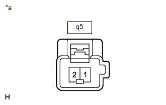
| (1) Check that the seat cushion moves smoothly when the auxiliary battery is connected to the front vertical motor connector terminals.
OK: |
Auxiliary Battery Connection |
Operational Direction | |
Auxiliary battery positive (+) → q5-1 Auxiliary battery negative (-) → q5-2 |
Seat cushion moves upward | |
Auxiliary battery positive (+) → q5-2 Auxiliary battery negative (-) → q5-1 |
Seat cushion moves downward | If the result is not as specified, replace the front seat adjuster assembly. |
 |
|
*a | Component without harness connected
(Front Vertical Motor (Front Seat Adjuster Assembly)) | | |
2. INSPECT FRONT SEATBACK FRAME SUB-ASSEMBLY
(a) Check the operation of the reclining motor.
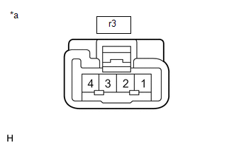
| (1) Check that the seatback moves smoothly when the auxiliary battery is connected to the reclining motor connector terminals.
OK: |
Auxiliary Battery Connection |
Operational Direction | |
Auxiliary battery positive (+) → r3-1 Auxiliary battery negative (-) → r3-4 |
Seatback moves forward | |
Auxiliary battery positive (+) → r3-4 Auxiliary battery negative (-) → r3-1 |
Seatback moves backward | If the result is not as specified, replace the front seatback frame sub-assembly. |
 |
|
*a | Component without harness connected
(Reclining Motor (Front Seatback Frame Sub-assembly)) | | |
READ NEXT:
REASSEMBLY CAUTION / NOTICE / HINT COMPONENTS (REASSEMBLY)
Procedure Part Name Code
1 SEAT TRACK REAR UPPER COVER
72125V -
- -
2 SEAT T
INSTALLATION CAUTION / NOTICE / HINT COMPONENTS (INSTALLATION)
Procedure Part Name Code
1 FRONT SEAT ASSEMBLY
-
- -
2 SEAT TRACK
SEE MORE:
Interior lights list
Location of the interior lights
Rear interior light
Door trim lights (if equipped)
Front interior/personal lights
Center tray light (if equipped)
Front cup holder light (if equipped)
Operating the interior
lights
■ Front
Turns the door position on/off
When a door
DESCRIPTION The stop light switch assembly is a duplex system that transmits two signals: STP and ST1-. These two signals are used by the hybrid vehicle control ECU to monitor whether or not the brake system is working properly. If the signals, which indicate the brake pedal is being depressed and r


